Fixing Planned Obsolescence: Converting a Mosquito Zapper to Li-ion
11th January, 2026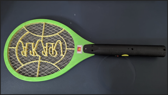
If you live in a tropical climate, the handheld mosquito zapper is a household staple. However, most commercial models suffer from a fundamental engineering flaw: the charging circuit.
Most bats use a transformer-less capacitive dropper circuit to charge a 4V sealed lead-acid (SLA) battery. There is no charge controller, no voltage cutoff, and no mercy for the chemistry inside. Leave it plugged in overnight once too often, and the battery bulges, loses capacity, and eventually dies.
In this post, we’ll gut the "dumb" electronics and replace them with a modern, protected Lithium-ion setup.
The Problem: "Dumb" Charging
The internal schematic of a standard zapper is terrifyingly simple. It uses a high-voltage capacitor to drop AC mains voltage down to a level that "trickles" into the battery.
Because there is no Charge Blocker, the battery is subjected to constant current even after reaching its chemical limit. This leads to:
- Electrolyte Breakdown: Generating internal gas.
- Casing Deformation: The dreaded "bulge."
- Plate Sulfation: Permanent loss of the "zap."
The Solution: The Protected Li-ion Upgrade
We are replacing the heavy SLA block with a 3.7V 1200mAh Li-ion cell and a TP4056 management module.
List of Materials
- Battery: 3.7V Li-ion (Affiliate link).
- Controller: TP4056 Module (Affiliate link).
- Connector: USB-C or Micro-USB (usually integrated into the TP4056).
Why the "Protected" Version?
The standard TP4056 handles the top-end (stopping at 4.2V). However, the protected version includes a DW01A IC and 8205A MOSFETs. This is crucial for:
- Under-voltage Protection: Cutting the load at 2.4V so you don't "brick" the cell.
- Short-circuit Protection: Handling the high-current spikes of the zapper transformer.
The Schematic
The wiring logic shifts from a serial AC-to-DC path to a parallel management path.
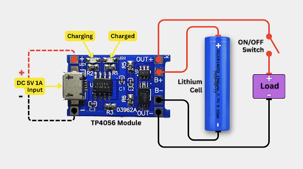
You must physically disconnect and remove the original AC charging pins. Never plug a modified bat into a wall socket.
Implementation Steps
-
Verification with a Multimeter
Before soldering, verify your cell's state of charge. On a 20V DC scale, a healthy lithium cell should read between 3.2V and 4.2V. If your meter reads 3.9V, you are at roughly 70% capacity—perfect for testing. -
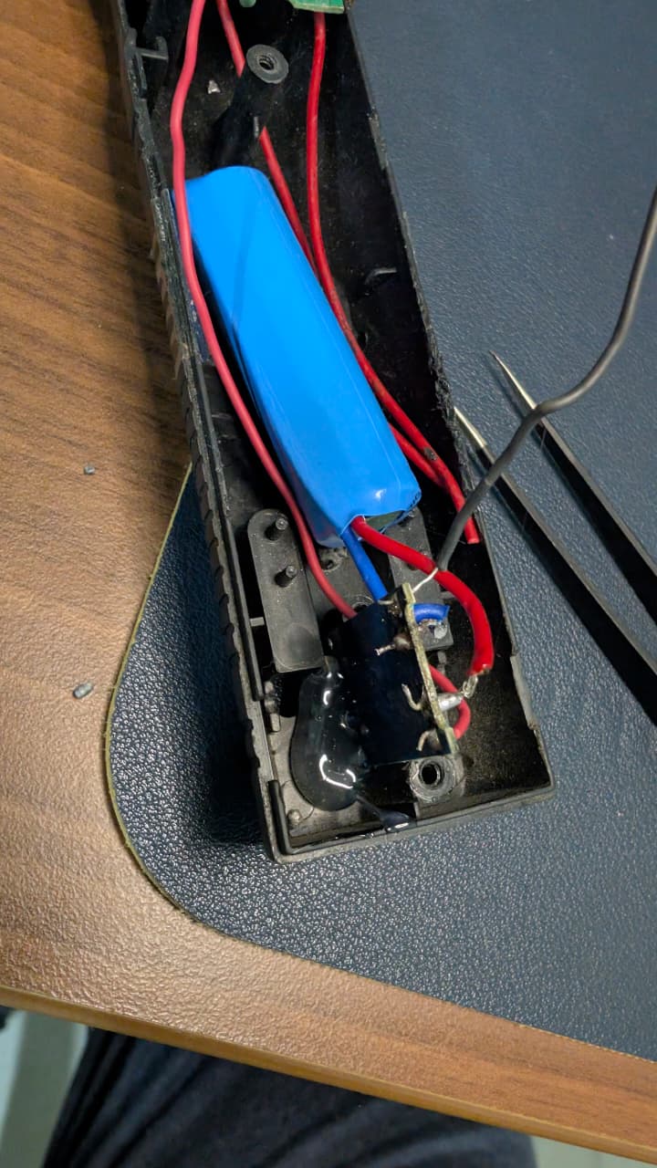
Bypassing the AC Stage
Snip the wires leading from the flip-out AC wall pins. These are now redundant. Locate the input terminals on the zapper PCB where the old battery was connected. This is where your OUT+ and OUT- will go. -
Soldering the Management Rail
Solder the battery leads to the B+ and B- pads. Solder the zapper PCB leads to the OUT+ and OUT- pads. Secure the TP4056 module to the handle casing using epoxy or high-temp hot glue. -
Calibration and Testing
Once connected, plug in the USB cable. You should see a Red LED, indicating the Constant Current phase. Once the battery hits exactly 4.2V, the Blue LED should trigger, signifying the charge blocker is active.
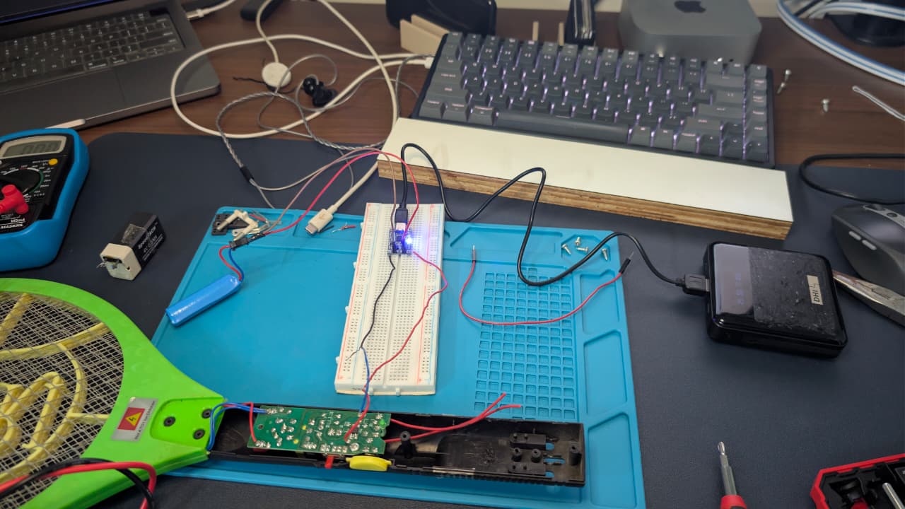
Testing on bread board before soldering
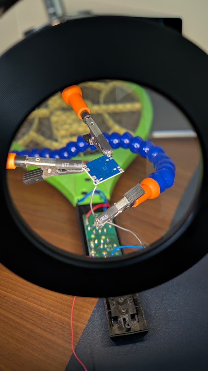
Soldering with helping hands and a magnifying glass
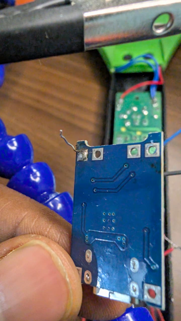
Successful solder of negaive (OUT -) of the board to negative (-) of the bat board
Hot glue to hold the board in place of the gap below so that the USB C is exposed and can be used for charging
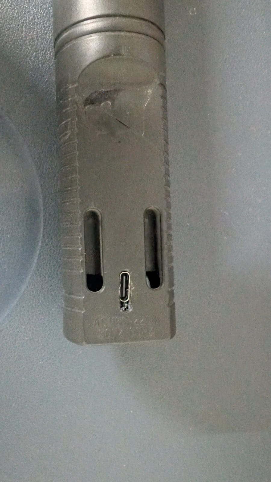
It looks like this from the outside where we once we have normal two pin charging
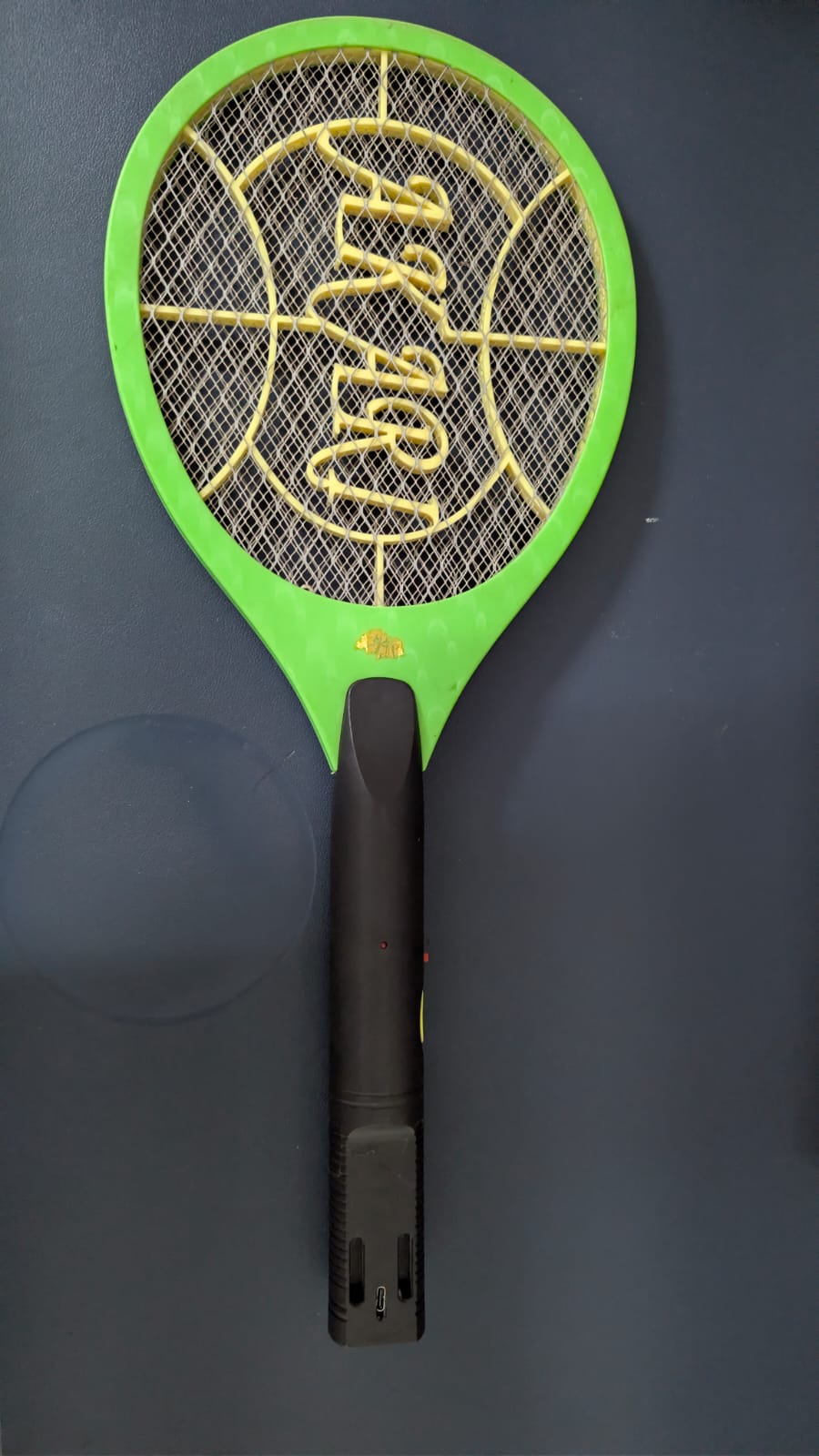
Fully assembled bat
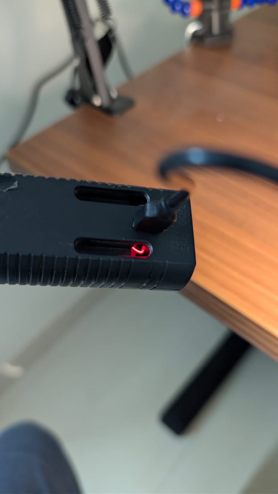
While charging the red light will glow
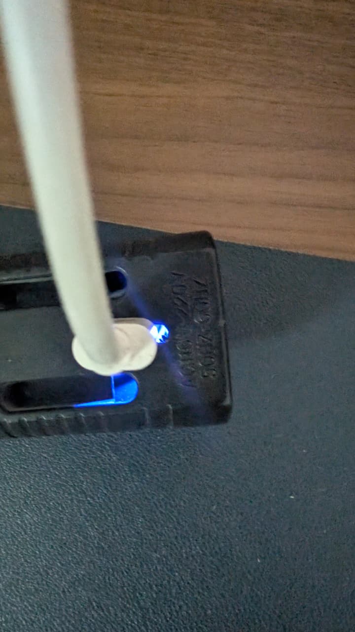
When fully charged the blue light will glow, after few seconds the light will be turned off
Performance Gains
Beyond safety, the performance delta is significant:
Internal Resistance: Li-ion has much lower ESR than lead-acid, allowing for a faster "dump" of energy into the transformer.
Weight: The bat becomes roughly 30% lighter and better balanced.
Longevity: With proper under-voltage protection, this cell will survive 500+ charge cycles, whereas the original SLA rarely survived 50.
Testing
- Idel battery drain - Tested the discharge cycle by enabling the switch in the bats circuit board that allows current to flow from battery, in 24 hrs saw a minor 0.08 V drop. I think we don't need to turn off that switch, but will keep testing in the long run on battery drain
Future improvements
- Using a Schottky diode to directly connect battery to bat circuit board instead of doing it through the TP4056 module
- Adding a polyfuse in series with battery which adds another safety layer against hard shorts